This site is from a past semester! The current version will be here when the new semester starts.
TIC4002 2021 Jan-May
  • Full Timeline
  • Week 1 [Mon, Jan 11th]
  • Week 2 [Fri, Jan 15th]
  • Week 3 [Fri, Jan 22nd]
  • Week 4 [Fri, Jan 29th]
  • Week 5 [Fri, Feb 5th]
  • Week 6 [Fri, Feb 12th]
  • Week 7 [Fri, Feb 19th]
  • Week 8 [Fri, Mar 5th]
  • Week 9 [Fri, Mar 12th]
  • Week 10 [Fri, Mar 19th]
  • Week 11 [Fri, Mar 26th]
  • Week 12 [Fri, Apr 2nd]
  • Week 13 [Fri, Apr 9th]
  • Textbook
  • Admin Info
  • Dashboards
  •  Individual Project (iP):
  • Individual Project Info
  • iP Upstream Repo
  • iP Showcase
  • iP Code Dashboard
  • iP Progress Dashboard

  •  Team Project (tP):
  • Team Project Info
  • tP Upstream Repo (AB3)
  • Team List
  • tP Code Dashboard
  • tP Progress Dashboard
  • Report Bugs
  • Forum
  • Instructors
  • Announcements
  • Files (handouts, submissions etc.)
  • MS Teams link
  • Java Coding Standard
  • Git Conventions
  • Participation Dashboard
  • Week 6 [Fri, Feb 12th] - Topics

    • [W6.1] Requirements: Use Cases, Glossary, NFRs

       Use Cases

    • [W6.1a] Requirements → Specifying Requirements → Use Cases → Introduction :

    • [W6.1b] Requirements → Specifying Requirements → Use Cases → Identifying :

    • [W6.1c] Requirements → Specifying Requirements → Use Cases → Details :

    • [W6.1d] Requirements → Specifying Requirements → Use Cases → Usage :

       Glossary

    • [W6.1e] Requirements → Specifying Requirements → Glossary → What :

       Supplementary Requirements

    • [W6.1f] Requirements → Specifying Requirements → Supplementary Requirements → What :

    • [W6.2] IDEs: Advanced Features
    • [W6.2a] Tools → IntelliJ IDEA → Productivity shortcuts :
    • [W6.3] Integration Approaches
    • [W6.3a] Implementation → Integration → Approaches → Late and one time versus early and frequent

    • [W6.3b] Implementation → Integration → Approaches → Big-bang versus incremental integration

    • [W6.3c] Implementation → Integration → Approaches → Top-down versus bottom-up integration : OPTIONAL

    • [W6.4] Writing Developer Documents

       Type of Developer Docs

    • [W6.4a] Implementation → Documentation → Introduction → What :

       Guideline: Aim for Comprehensibility

    • [W6.4b] Implementation → Documentation → Guidelines → Aim for Comprehensibility → What :

    • [W6.4c] Implementation → Documentation → Guidelines → Aim for Comprehensibility → How :

       Guideline: Describe Top-Down

    • [W6.4d] Implementation → Documentation → Guidelines → Describe Top-Down → What

    • [W6.4e] Implementation → Documentation → Guidelines → Describe Top-Down → Why

    • [W6.4f] Implementation → Documentation → Guidelines → Describe Top-Down → How

       Guideline: Minimal but Sufficient

    • [W6.4g] Implementation → Documentation → Guidelines → Minimal but Sufficient → What :

    • [W6.4h] Implementation → Documentation → Guidelines → Minimal but Sufficient → How :


    [W6.1] Requirements: Use Cases, Glossary, NFRs

    Video


    Use Cases

    W6.1a :

    Requirements → Specifying Requirements → Use Cases → Introduction

    Can explain use cases

    Use case: A description of a set of sequences of actions, including variants, that a system performs to yield an observable result of value to an actor.[ 📖 : uml-user-guideThe Unified Modeling Language User Guide, 2e, G Booch, J Rumbaugh, and I Jacobson ]

    Actor: An actor (in a use case) is a role played by a user. An actor can be a human or another system. Actors are not part of the system; they reside outside the system.

    A use case describes an interaction between the user and the system for a specific functionality of the system.

    System: Online Banking System (OBS)
    Use case: UC23 - Transfer Money
    Actor: User
    MSS:
      1. User chooses to transfer money.
      2. OBS requests for details of the transfer.
      3. User enters the requested details.
      4. OBS requests for confirmation.
      5. User confirms.
      6. OBS transfers the money and displays the new account balance.
      Use case ends.
    
    Extensions:
      3a. OBS detects an error in the entered data.
          3a1. OBS requests for the correct data.
          3a2. User enters new data.
          Steps 3a1-3a2 are repeated until the data entered are correct.
          Use case resumes from step 4.
      
      3b. User requests to effect the transfer in a future date.
          3b1. OBS requests for confirmation.
          3b2. User confirms future transfer.
          Use case ends.
      
      *a. At any time, User chooses to cancel the transfer.
          *a1. OBS requests to confirm the cancellation.
          *a2. User confirms the cancellation.
          Use case ends.
    
    • System: A Learning Management System (LMS)
    • Actor: Student
    • Use Case: Upload file
      1. Student requests to upload file
      2. LMS requests for the file location
      3. Student specifies the file location
      4. LMS uploads the file

    UML includes a diagram type called use case diagrams that can illustrate use cases of a system visually, providing a visual ‘table of contents’ of the use cases of a system.

    In the example on the right, note how use cases are shown as ovals and user roles relevant to each use case are shown as stick figures connected to the corresponding ovals.

    Unified Modeling Language (UML) is a graphical notation to describe various aspects of a software system. UML is the brainchild of three software modeling specialists James Rumbaugh, Grady Booch and Ivar Jacobson (also known as the Three Amigos). Each of them had developed their own notation for modeling software systems before joining forces to create a unified modeling language (hence, the term ‘Unified’ in UML). UML is currently the de facto modeling notation used in the software industry.

    Use cases capture the functional requirements of a system.

    W6.1b :

    Requirements → Specifying Requirements → Use Cases → Identifying

    Can use use cases to list functional requirements of a simple system

    A use case is an interaction between a system and its actors.

    Actors in Use Cases

    Actor: An actor (in a use case) is a role played by a user. An actor can be a human or another system. Actors are not part of the system; they reside outside the system.

    Some example actors for a Learning Management System:

    • Actors: Guest, Student, Staff, Admin, an exam management systemExamSys, a library management systemLibSys.

    A use case can involve multiple actors.

    • Software System: LearnSys
    • Use case: UC01 Conduct Survey
    • Actors: Staff, Student

    An actor can be involved in many use cases.

    • Software System: LearnSys
    • Actor: Staff
    • Use cases: UC01 Conduct Survey, UC02 Set Up Course Schedule, UC03 Email Class, ...

    A single person/system can play many roles.

    • Software System: LearnSys
    • Person: a student
    • Actors (or Roles): Student, Guest, Tutor

    Many persons/systems can play a single role.

    • Software System: LearnSys
    • Actor (or role): Student
    • Persons that can play this role: undergraduate student, graduate student, a staff member doing a part-time course, exchange student

    Use cases can be specified at various levels of detail.

    Consider the three use cases given below. Clearly, (a) is at a higher level than (b) and (b) is at a higher level than (c).

    • System: LearnSys
    • Use cases:
      a. Conduct a survey
      b. Take the survey
      c. Answer survey question

    While modeling user-system interactions,

    • Start with high level use cases and progressively work toward lower level use cases.
    • Be mindful of which level of detail you are working at and not to mix use cases of different levels.

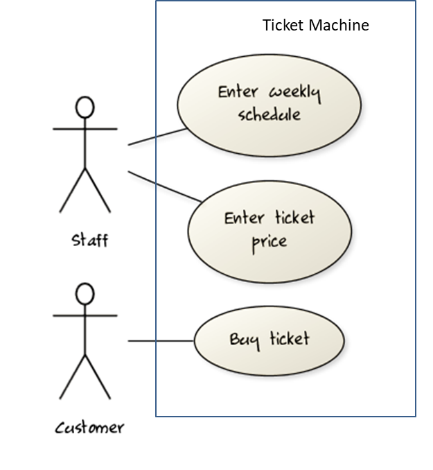
    Consider a simple movie ticket vending machine application. Every week, the theatre staff will enter the weekly schedule as well as ticket price for each show. A customer sees the schedule and the ticket price displayed at the machine. There is a slot to insert money, a keypad to enter a code for a movie, a code for the show time, and the number of tickets. A display shows the customer's balance inside the machine. A customer may choose to cancel a transaction before pressing the “buy” button. Printed tickets can be collected from a slot at the bottom of the machine. The machine also displays messages such as "Please enter more money”, “Request fewer tickets" or "SOLD OUT!”. Finally, a "Return Change" button allows the customer to get back his unspent money.

    Draw a use case diagram for the above requirements.

    Note that most of the details in the description are better given as part of the use case description rather than as low-level use cases in the diagram.

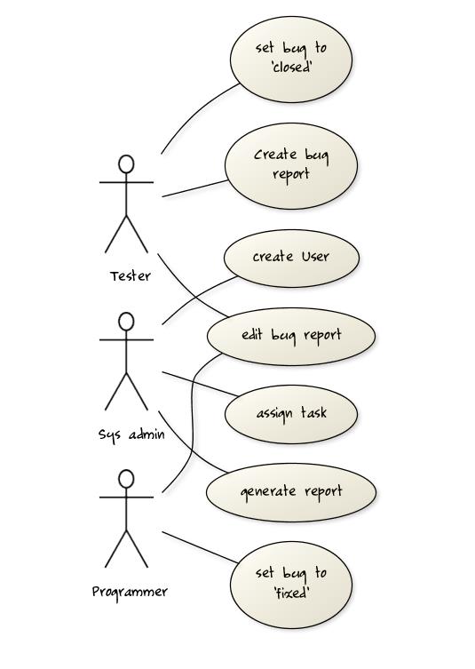
    A software house wishes to automate its Quality Assurance division.

    The system is to be used by Testers, Programmers and System Administrators. Only an administrator can create new users and assign tasks to programmers. Any tester can create a bug report, as well as set the status of a bug report as ‘closed’. Only a programmer can set the state of a bug report to ‘fixed’, but a programmer cannot set the status of a bug report to ‘closed’. Each tester is assigned just one task at a time. A task involves testing of a particular component for a particular customer. Tester must document the bugs they find. Each bug is given a unique identifier. Other information recorded about the bug is component id, severity, date and time reported, programmer who is assigned to fix it, date fixed, date retested and date closed. The system keeps track of which bugs are assigned to which programmer at any given time. It should be able to generate reports on the number of bugs found, fixed and closed e.g. number of bugs per component and per customer; number of bugs found by a particular tester; number of bugs awaiting to be fixed; number of bugs awaiting to be retested; number of bugs awaiting to be assigned to programmers etc.

    Develop a use case diagram to capture their requirements given below.

    Explanation: The given description contains information not relevant to use case modeling. Furthermore, the description is not enough to complete the use case diagram. All these are realities of real projects. However, the process of trying to create this use case diagram prompts us to investigate issues such as:

    • Is ‘edit bug report’ a use case or is editing the bug report covered by other use cases such as those for setting the status of bug reports? If it is indeed a separate use case, who are the actors of that use case?
    • Does ‘assign task’ simply mean ‘assign bug report’ or are there other types of tasks?
    • There was some mention about Customers and Components. Does the system have to support use cases for creating and maintaining details about those entities? For example, should we have a ‘create customer record’ use case?
    • Which actors can perform the ‘generate report’ use case? Are reports generated automatically by the system at a specific time or generated ‘on demand’ when users request to view them? Do we have to treat different types of reports as different use cases (in case some types of reports are restricted to some types of users)? The above diagram assumes (just for illustration) that the report is generated on demand and only the system admin can generate any report.

    W6.1c :

    Requirements → Specifying Requirements → Use Cases → Details

    Can specify details of a use case in a structured format

    Writing use case steps

    The main body of the use case is a sequence of steps that describes the interaction between the system and the actors. Each step is given as a simple statement describing who does what.

    An example of the main body of a use case.

    1. Student requests to upload file
    2. LMS requests for the file location
    3. Student specifies the file location
    4. LMS uploads the file

    A use case describes only the externally visible behavior, not internal details, of a system i.e. should minimize details that are not part of the interaction between the user and the system.

    This example use case step refers to behaviors not externally visible.

    1. LMS saves the file into the cache and indicates success.

    A step gives the intention of the actor (not the mechanics). That means UI details are usually omitted. The idea is to leave as much flexibility to the UI designer as possible. That is, the use case specification should be as general as possible (less specific) about the UI.

    The first example below is not a good use case step because it contains UI-specific details. The second one is better because it omits UI-specific details.

    Bad : User right-clicks the text box and chooses ‘clear’

    Good : User clears the input

    A use case description can show loops too.

    An example of how you can show a loop:

    Software System: SquareGame
    Use case: Each use case can be given a unique identification for easier cross reference. UC02 - Play a Game
    Actors: Player (multiple players)

    1. A Player starts the game.
    2. SquareGame asks for player names.
    3. Each Player enters his own name.
    4. SquareGame shows the order of play.
    5. SquareGame prompts for the current Player to throw a die.
    6. Current Player adjusts the throw speed.
    7. Current Player triggers the die throw.
    8. SquareGame shows the face value of the die.
    9. SquareGame moves the Player's piece accordingly.
      Steps 5-9 are repeated for each Player, and for as many rounds as required until a Player reaches the 100th square.
    10. SquareGame shows the Winner.

    Use case ends.

    The Main Success Scenario (MSS) describes the most straightforward interaction for a given use case, which assumes that nothing goes wrong. This is also called the Basic Course of Action or the Main Flow of Events of a use case.

    Note how the MSS in the example below assumes that all entered details are correct and ignores problems such as timeouts, network outages etc. For example, the MSS does not tell us what happens if the user enters incorrect data.

    System: Online Banking System (OBS)
    Use case: UC23 - Transfer Money
    Actor: User
    MSS:

    1. User chooses to transfer money.
    2. OBS requests for details of the transfer.
    3. User enters the requested details.
    4. OBS requests for confirmation.
    5. OBS transfers the money and displays the new account balance.

    Use case ends.

    Extensions are "add-on"s to the MSS that describe exceptional/alternative flow of events. They describe variations of the scenario that can happen if certain things are not as expected by the MSS. Extensions appear below the MSS.

    This example adds some extensions to the use case in the previous example.

    System: Online Banking System (OBS)
    Use case: UC23 - Transfer Money
    Actor: User
    MSS:
      1. User chooses to transfer money.
      2. OBS requests for details of the transfer.
      3. User enters the requested details.
      4. OBS requests for confirmation.
      5. User confirms.
      6. OBS transfers the money and displays the new account balance.
      Use case ends.
    
    Extensions:
      3a. OBS detects an error in the entered data.
          3a1. OBS requests for the correct data.
          3a2. User enters new data.
          Steps 3a1-3a2 are repeated until the data entered are correct.
          Use case resumes from step 4.
      
      3b. User requests to effect the transfer in a future date.
          3b1. OBS requests for confirmation.
          3b2. User confirms future transfer.
          Use case ends.
      
      *a. At any time, User chooses to cancel the transfer.
          *a1. OBS requests to confirm the cancellation.
          *a2. User confirms the cancellation.
          Use case ends.
    
      *b. At any time, 120 seconds lapse without any input from the User.
          *b1. OBS cancels the transfer.
          *b2. OBS informs the User of the cancellation.
          Use case ends.
    

    Note that the numbering style is not a universal rule but a widely used convention. Based on that convention,

    • either of the extensions marked 3a. and 3b. can happen just after step 3 of the MSS.
    • the extension marked as *a. can happen at any step (hence, the *).

    When separating extensions from the MSS, keep in mind that the MSS should be self-contained. That is, the MSS should give us a complete usage scenario.

    Also note that it is not useful to mention events such as power failures or system crashes as extensions because the system cannot function beyond such catastrophic failures.

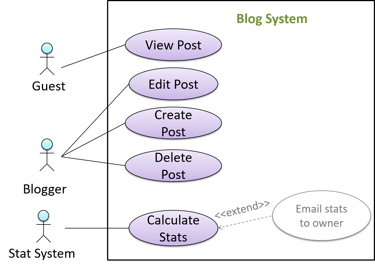
    In use case diagrams you can use the <<extend>> arrows to show extensions. Note the direction of the arrow is from the extension to the use case it extends and the arrow uses a dashed line.

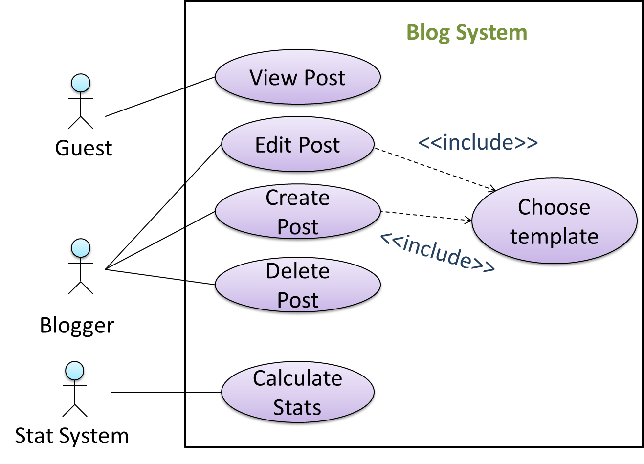
    A use case can include another use case. Underlined text is commonly used to show an inclusion of a use case.

    This use case includes two other use cases, one in step 1 and one in step 2.

    • Software System: LearnSys
    • Use case: UC01 - Conduct Survey
    • Actors: Staff, Student
    • MSS:
      1. Staff creates the survey (UC44).
      2. Student completes the survey (UC50).
      3. Staff views the survey results.
        Use case ends.

    Inclusions are useful,

    • when you don't want to clutter a use case with too many low-level steps.
    • when a set of steps is repeated in multiple use cases.

    You use a dotted arrow and an <<include>> annotation to show use case inclusions in a use case diagram. Note how the arrow direction is different from the <<extend>> arrows.

    Preconditions specify the specific state you expect the system to be in before the use case starts.

    Software System: Online Banking System
    Use case: UC23 - Transfer Money
    Actor: User
    Preconditions: User is logged in
    MSS:

    1. User chooses to transfer money.
    2. OBS requests for details for the transfer.
      ...

    Guarantees specify what the use case promises to give us at the end of its operation.

    Software System: Online Banking System
    Use case: UC23 - Transfer Money
    Actor: User
    Preconditions: User is logged in.
    Guarantees:

    • Money will be deducted from the source account only if the transfer to the destination account is successful.
    • The transfer will not result in the account balance going below the minimum balance required.

    MSS:

    1. User chooses to transfer money.
    2. OBS requests for details for the transfer.
      ...

    Complete the following use case (MSS, extensions, etc.). Note that you should not blindly follow how the existing A type of a cash card topup machineEZ-Link machine operates because it will prevent you from designing a better system. You should consider all possible extensions without complicating the use case too much.

    • System: EZ-Link machine
    • Use case: UC01 top-up EZ-Link card
    • Actor: EZ-Link card user
    • System: EZ-Link machine (those found at MRTs)
    • Use case: UC01 top-up EZ-Link card
    • Actor: EZ-Link card user
    • Preconditions: All hardware in working order.
    • Guarantees: MSS → the card will be topped-up.
    • MSS:
      1. User places the card on the reader.
      2. System displays card details and prompts for desired action.
      3. User selects top-up.
      4. System requests for top-up details (amount, payment option, receipt required?).
      5. User enters details.
      6. System processes cash payment (UC02) or NETS payment (UC03).
      7. System updates the card value.
      8. System indicates transaction as completed.
      9. If requested in step 5, system prints receipt.
      10. User removes the card.
      11. Use case ends.
    • Extensions:
      1. *a. User removed card or other hardware error detected.
        1. *a1. System indicates the transaction has been aborted.
        2. Use case ends.

    Notes:

    • We assume that the only way to cancel a transaction is by removing the card.
    • By not breaking step 4 into further steps, we avoid committing to a particular mechanism to enter data. For example, we are free to accept all data in one screen.
    • In step 5, we assume that the input mechanism does not allow any incorrect data.
    • System: EZ-Link machine
    • Use case: UC03 process NETS payment
    • Actor: EZ-Link card user
    • Preconditions: A transaction requiring payment is underway.
    • Guarantees: MSS → Transaction amount is transferred from user account to EZ-Link company account.
    • MSS:
      1. System requests to insert ATM card.
      2. User inserts the ATM card.
      3. System requests for PIN.
      4. User enters PIN.
      5. System reports success.
      6. Use case ends.
    • Extensions:
      1. 2a. Unacceptable ATM card (damaged or inserted wrong side up).
        1. ...
      2. 4a. Wrong PIN.
        1. ...
      3. 4b. Insufficient funds.
        1. ...
      4. *a. Connection to the NETS gateway is disrupted.
        1. ...

    Note: UC02 can be written along similar lines.

    Complete the following use case (MSS, extensions, etc.).

    • System: LearnSys (an online Learning Management System)
    • Use case: UC01 reply to post in the forum
    • Actor: Student
    • System: LearnSys
    • Use case: UC01 reply to post in the forum
    • Actor: Student
    • Preconditions: Student is logged in and has permission to post in the forum. The post to which the Student replies already exists.
    • MSS:
      1. Student chooses to reply to an existing post.
      2. LearnSys requests the user to enter post details.
      3. Student enters post details.
      4. Student submits the post.
      5. LearnSys displays the post.
      6. Use case ends.
    • Extensions:
      1. *a. Internet connection goes down.
        1. ...
      2. *b. LearnSys times out
        1. ...
      3. 3a. Student chooses to ‘preview’ the post.
        1. 3a1. LearnSys shows a preview.
        2. 3a2. User chooses to go back to editing.
        3. Use case resumes at step 3.
      4. 3b. Student chooses to attach picture/file
        1. ...
      5. 3c. Student chooses to save the post as a draft.
        1. 3c1. LearnSys confirms draft has been saved.
        2. Use case ends.
      6. 3d. Student chooses to abort the operation.
        1. ...
      7. 4a. The post being replied to is deleted by the owner while the reply is being entered.
        1. ...
      8. 4b. Unacceptable data entered.
        1. ...

    Which of these cannot appear as part of a use case description?

    • a. Use case identifier
    • b. Preconditions
    • c. Guarantees
    • d. References to another use case
    • e. Main Success Scenario
    • f. Performance requirements
    • g. Extensions
    • h. Inclusions

    (f)

    Explanation: Performance requirements are non-functional requirements. They are not captured in use cases.

    Identify problems with this use case description.

    • System: EZ-Link machine (those found at MRTs)
    • Use case: UC01 top-up EZ-Link card
    • Actor: EZ-Link card user
    • Preconditions: All hardware in working order.
    • Guarantees: If MSS completes at least until step 7, the card will be topped-up.
    • MSS:
      1. User places the card on the reader.
      2. System displays card details and prompts for desired action.
      3. User selects top-up.
      4. System requests for top-up details (amount, payment option, receipt required?).
      5. User enters details.
      6. System processes cash payment (UC02) or NETS payment (UC03).
      7. System updates the card value.
      8. System indicates transaction as completed.
      9. If requested in step 5, system prints receipt.
      10. User removes the card.
      11. Use case ends.
    • Extensions:
      1. *a. User removed card or other hardware error detected.
        1. *a1. System indicates the transaction has been aborted.
        2. Use case ends.
    • a. It does not consider ‘system crash’ scenario.
    • b. It does not contain enough UI details.
    • c. The extension given is in fact an inclusion.
    • d. No post conditions are given.
    • e. ‘Use case ends’ is duplicated.

    None.

    Explanation: Catastrophic failures such as ‘system crash’ need not be included in a use case. A use case is not supposed to contain UI details. Post conditions are optional. It is not a problem to have multiple exit points for a use case.

    W6.1d :

    Requirements → Specifying Requirements → Use Cases → Usage

    Can optimize the use of use cases

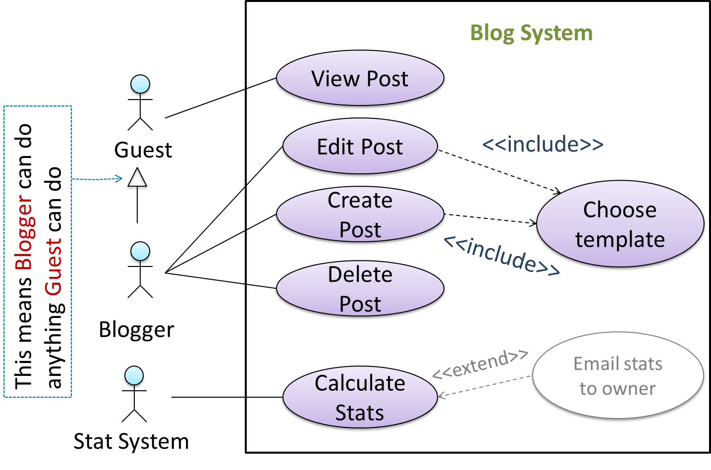
    You can use actor generalization in use case diagrams using a symbol similar to that of UML notation for inheritance.

    In this example, actor Blogger can do all the use cases the actor Guest can do, as a result of the actor generalization relationship given in the diagram.

    Do not over-complicate use case diagrams by trying to include everything possible. A use case diagram is a brief summary of the use cases that is used as a starting point. Details of the use cases can be given in the use case descriptions.

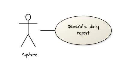
    Some include ‘System’ as an actor to indicate that something is done by the system itself without being initiated by a user or an external system.

    The diagram below can be used to indicate that the system generates daily reports at midnight.

    However, others argue that only use cases providing value to an external user/system should be shown in the use case diagram. For example, they argue that view daily report should be the use case and generate daily report is not to be shown in the use case diagram because it is simply something the system has to do to support the view daily report use case.

    You are recommended to follow the latter view (i.e. not to use System as a user). Limit use cases for modeling behaviors that involve an external actor.

    UML is not very specific about the text contents of a use case. Hence, there are many styles for writing use cases. For example, the steps can be written as a continuous paragraph.

    Use cases should be easy to read. Note that there is no strict rule about writing all details of all steps or a need to use all the elements of a use case.

    There are some advantages of documenting system requirements as use cases:

    • Because they use a simple notation and plain English descriptions, they are easy for users to understand and give feedback.
    • They decouple user intention from mechanism (note that use cases should not include UI-specific details), allowing the system designers more freedom to optimize how a functionality is provided to a user.
    • Identifying all possible extensions encourages us to consider all situations that a software product might face during its operation.
    • Separating typical scenarios from special cases encourages us to optimize the typical scenarios.

    One of the main disadvantages of use cases is that they are not good for capturing requirements that do not involve a user interacting with the system. Hence, they should not be used as the sole means to specify requirements.

    What are the advantages of using use cases (the textual form) for requirements modelling?

    • a. They can be fairly detailed but still natural enough for users to understand and give feedback.
    • b. The UI-independent nature of use case specification allows the system designers more freedom to decide how a functionality is provided to a user.
    • c. Extensions encourage us to consider all situations a software product might face during its operations.
    • d. They encourage us to identify and optimize the typical scenario of usage over exceptional usage scenarios.

    (a) (b) (c) (d)

    Which of these are correct?

    • a. Use cases are not very suitable for capturing non-functional requirements.
    • b. Use case diagrams are less detailed than textual use cases.
    • c. Use cases are better than user stories.
    • d. Use cases can be expressed at different levels of abstraction.

    (a)(b)(d)

    Explanation: It is not correct to say one format is better than the other. It depends on the context.


    Glossary

    W6.1e :

    Requirements → Specifying Requirements → Glossary → What

    Can explain glossary

    Glossary: A glossary serves to ensure that all stakeholders have a common understanding of the noteworthy terms, abbreviations, acronyms etc.

    Here is a partial glossary from a variant of the Snakes and Ladders game:

    • Conditional square: A square that specifies a specific face value which a player has to throw before his/her piece can leave the square.
    • Normal square: a normal square does not have any conditions, snakes, or ladders in it.


    Supplementary Requirements

    W6.1f :

    Requirements → Specifying Requirements → Supplementary Requirements → What

    Can explain supplementary requirements

    A supplementary requirements section can be used to capture requirements that do not fit elsewhere. Typically, this is where most Non-Functional Requirements will be listed.

    Requirements → Requirements →

    Non-functional requirements

    Requirements can be divided into two in the following way:

    1. Functional requirements specify what the system should do.
    2. Non-functional requirements specify the constraints under which the system is developed and operated.

    Some examples of non-functional requirement categories:

    • Data requirements e.g. size, how often do data changevolatility, saving data permanentlypersistency etc.,
    • Environment requirements e.g. technical environment in which the system would operate in or needs to be compatible with.
    • Accessibility, Capacity, Compliance with regulations, Documentation, Disaster recovery, Efficiency, Extensibility, Fault tolerance, Interoperability, Maintainability, Privacy, Portability, Quality, Reliability, Response time, Robustness, Scalability, Security, Stability, Testability, and more ...
    • Business/domain rules: e.g. the size of the minefield cannot be smaller than five.
    • Constraints: e.g. the system should be backward compatible with data produced by earlier versions of the system; system testers are available only during the last month of the project; the total project cost should not exceed $1.5 million.
    • Technical requirements: e.g. the system should work on both 32-bit and 64-bit environments.
    • Performance requirements: e.g. the system should respond within two seconds.
    • Quality requirements: e.g. the system should be usable by a novice who has never carried out an online purchase.
    • Process requirements: e.g. the project is expected to adhere to a schedule that delivers a feature set every one month.
    • Notes about project scope: e.g. the product is not required to handle the printing of reports.
    • Any other noteworthy points: e.g. the game should not use images deemed offensive to those injured in real mine clearing activities.

    You may have to spend an extra effort in digging NFRs out as early as possible because,

    1. NFRs are easier to miss e.g., stakeholders tend to think of functional requirements first
    2. sometimes NFRs are critical to the success of the software. E.g. A web application that is too slow or that has low security is unlikely to succeed even if it has all the right functionality.

    Given below are some requirements of TEAMMATES (an online peer evaluation system for education). Which one of these are non-functional requirements?

    • a. The response to any use action should become visible within 5 seconds.
    • b. The application admin should be able to view a log of user activities.
    • c. The source code should be open source.
    • d. A course should be able to have up to 2000 students.
    • e. As a student user, I can view details of my team members so that I can know who they are.
    • f. The user interface should be intuitive enough for users who are not IT-savvy.
    • g. The product is offered as a free online service.

    (a)(c)(d)(f)(g)

    Explanation: (b) are (e) are functions available for a specific user types. Therefore, they are functional requirements. (a), (c), (d), (f) and (g) are either constraints on functionality or constraints on how the project is done, both of which are considered non-functional requirements.
    [W6.2] IDEs: Advanced Features

    W6.2a :

    Tools → IntelliJ IDEA → Productivity shortcuts

    Can use some useful IDE productivity shortcuts

    [W6.3] Integration Approaches

    Video

    W6.3a

    Implementation → Integration → Approaches → Late and one time versus early and frequent

    Can explain how integration approaches vary based on timing and frequency

    In terms of timing and frequency, there are two general approaches to integration: late and one-time, early and frequent.

    Late and one-time: wait till all components are completed and integrate all finished components near the end of the project.

    This approach is not recommended because integration often causes many component incompatibilities (due to previous miscommunications and misunderstandings) to surface which can lead to delivery delays i.e. Late integration → incompatibilities found → major rework required → cannot meet the delivery date.

    Early and frequent: integrate early and evolve each part in parallel, in small steps, re-integrating frequently.

    A it has all the high-level components needed for the first version in their minimal form, compiles, and runs but may not produce any useful output yetwalking skeleton can be written first. This can be done by one developer, possibly the one in charge of integration. After that, all developers can flesh out the skeleton in parallel, adding one feature at a time. After each feature is done, simply integrate the new code into the main system.

    Here is an animation that compares the two approaches:

    W6.3b

    Implementation → Integration → Approaches → Big-bang versus incremental integration

    Can explain how integration approaches vary based on amount merged at a time

    Big-bang integration: integrate all components at the same time.

    Big-bang is not recommended because it will uncover too many problems at the same time which could make debugging and bug-fixing more complex than when problems are uncovered incrementally.

    Incremental integration: integrate a few components at a time. This approach is better than big-bang integration because it surfaces integration problems in a more manageable way.

    Here is an animation that compares the two approaches:

    Give two arguments in support and two arguments against the following statement.

    Because there is no external client, it is OK to use big bang integration for a school project.

    Arguments for:

    • It is relatively simple; even big-bang can succeed.
    • Project duration is short; there is not enough time to integrate in steps.
    • The system is non-critical, non-production (demo only); the cost of integration issues is relatively small.

    Arguments against:

    • Inexperienced developers; big-bang more likely to fail.
    • Too many problems may be discovered too late. Submission deadline (fixed) can be missed.
    • Team members have not worked together before; increases the probability of integration problems.

    W6.3c : OPTIONAL

    Implementation → Integration → Approaches → Top-down versus bottom-up integration

    Can explain how integration approaches vary based on the order of integration

    Based on the order in which components are integrated, incremental integration can be done in three ways.

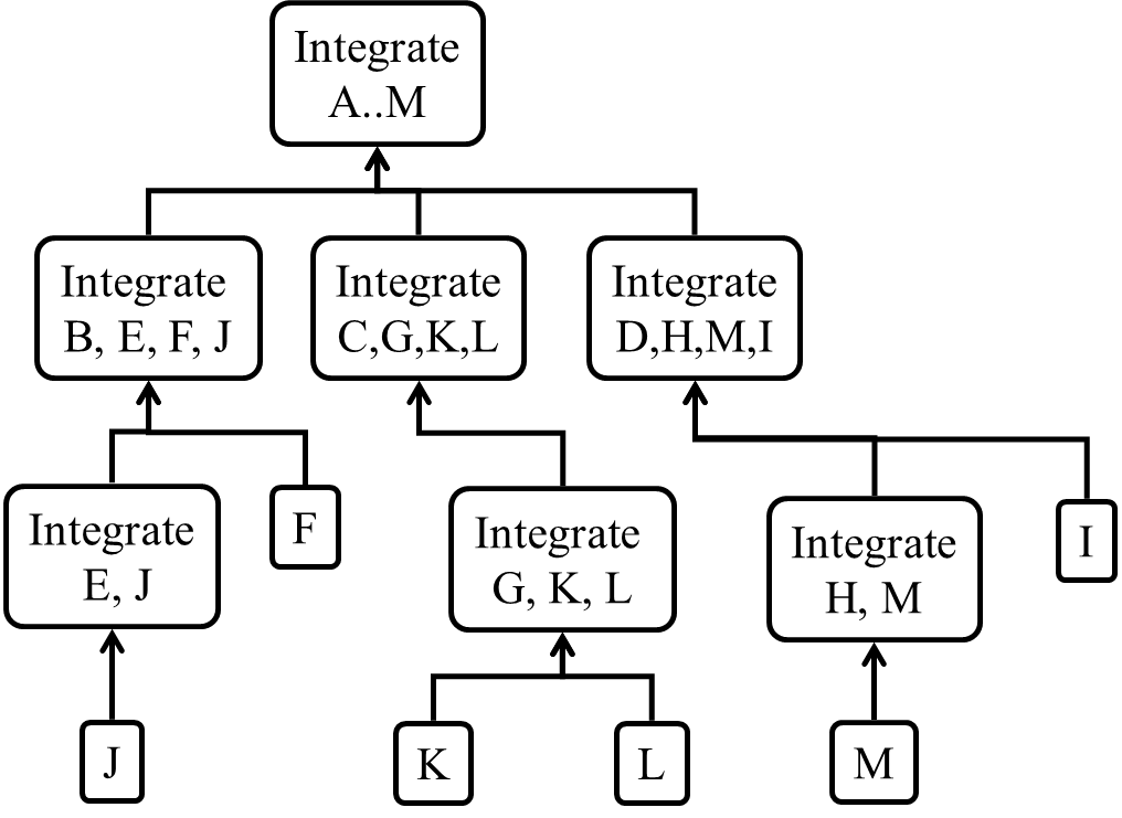
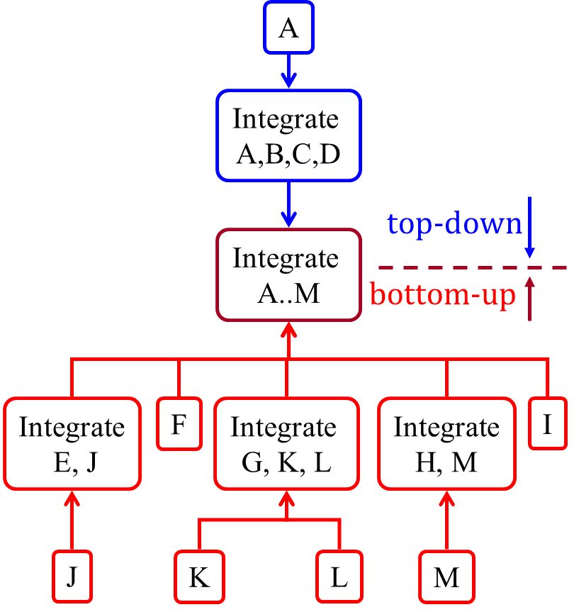
    Top-down integration: higher-level components are integrated before bringing in the lower-level components. One advantage of this approach is that higher-level problems can be discovered early. One disadvantage is that this requires the use of stubs in place of lower level components until the real lower-level components are integrated into the system. Otherwise, higher-level components cannot function as they depend on lower level ones.

    Stub: A stub has the same interface as the component it replaces, but its implementation is so simple that it is unlikely to have any bugs. It mimics the responses of the component, but only for a limited set of predetermined inputs. That is, it does not know how to respond to any other inputs. Typically, these mimicked responses are hard-coded in the stub rather than computed or retrieved from elsewhere, e.g. from a database.

    Bottom-up integration: the reverse of top-down integration. Note that when integrating lower level components, additional code written to provide inputs to a component via an APIdrivers may be needed to test the integrated components because the UI may not be integrated yet, just like how top-down integration needs stubs.

    Sandwich integration: a mix of the top-down and bottom-up approaches. The idea is to do both top-down and bottom-up so as to 'meet' in the middle.

    Here is an animation that compares the three approaches:

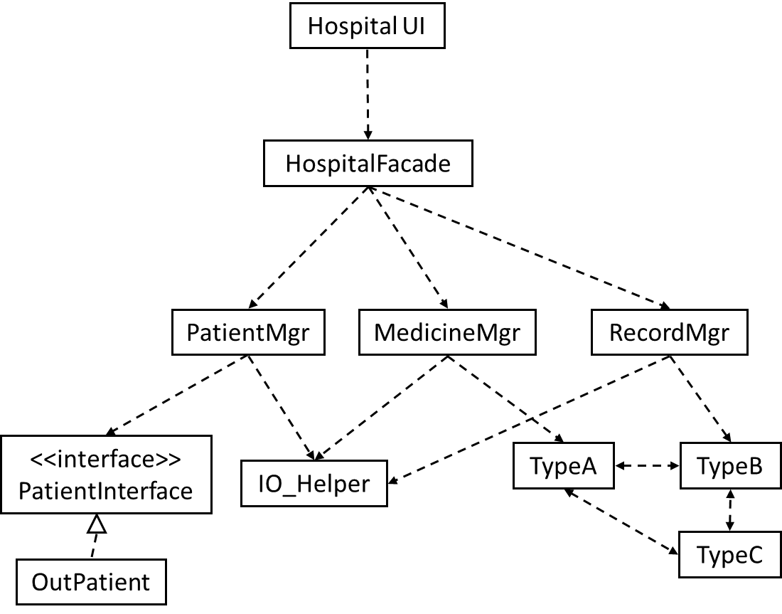
    Suggest an integration strategy for the system represented by the following diagram. You need not follow a strict top-down, bottom-up, sandwich, or big bang approach. Dashed arrows represent dependencies between classes.

    Also take into account the following facts in your test strategy:

    • HospitalUI will be developed early, so as to get customer feedback early.
    • HospitalFacade shields the UI from the complexities of the application layer. It simply redirects the method calls received to the appropriate classes below.
    • IO_Helper is to be reused from an earlier project, with minor modifications.
    • Development of the OutPatient component has been outsourced, and its delivery is not expected until the 2nd half of the project.

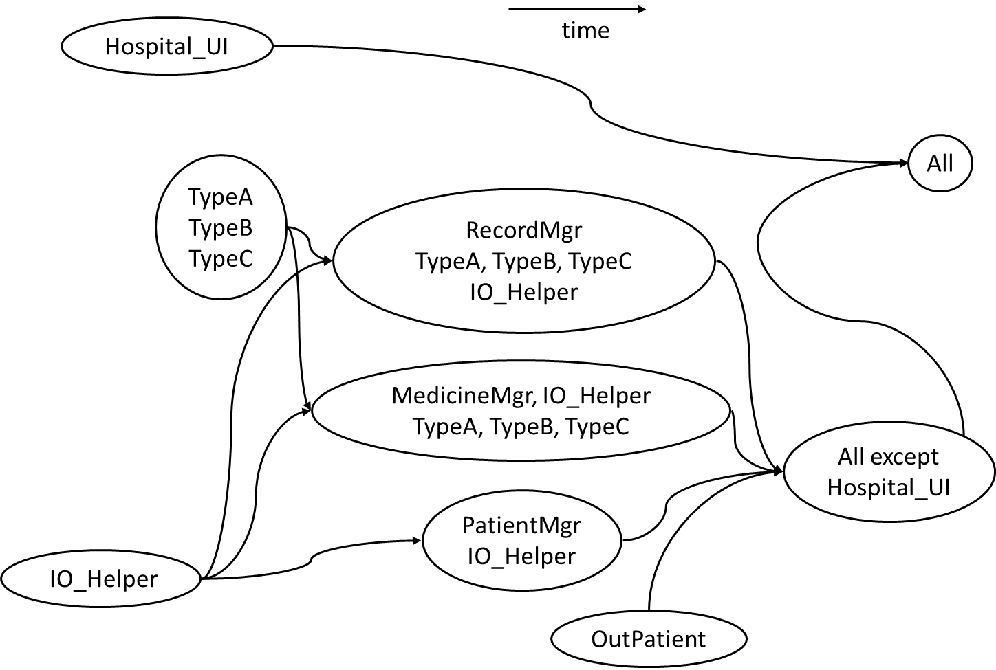
    There can be many acceptable answers to this question. But any good strategy should consider at least some of the following:

    • Because HospitalUI will be developed early, it’s OK to integrate it early, using stubs, rather than wait for the rest of the system to finish. (i.e. a top-down integration is suitable for HospitalUI)
    • Because HospitalFacade is unlikely to have a lot of business logic, it may not be worth to write stubs to test it (i.e. a bottom-up integration is better for HospitalFacade).
    • Because IO_Helper is to be reused from an earlier project, you can finish it early. This is especially suitable since there are many classes that use it. Therefore IO_Helper can be integrated with the dependent classes in bottom-up fashion.
    • Because the OutPatient class may be delayed, you may have to integrate PatientMgr using a stub.
    • TypeA, TypeB, and TypeC seem to be tightly coupled. It may be a good idea to test them together.

    Given below is one possible integration test strategy. The relative positioning of items is used to indicate a rough timeline.

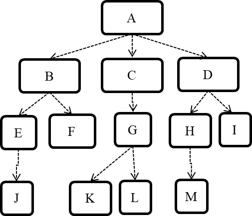
    Consider the architecture given below. Describe the order in which components will be integrated with one another if the following integration strategies were adopted.

    a) top-down
    b) bottom-up
    c) sandwich

    Note that dashed arrows show dependencies (e.g. A depends on B, C and D, and is therefore higher-level than B, C and D).

    a) Diagram:

    b) Diagram:

    c) Diagram:

    [W6.4] Writing Developer Documents

    Video


    Type of Developer Docs

    W6.4a :

    Implementation → Documentation → Introduction → What

    Can explain the two types of developer docs

    Developer-to-developer documentation can be in one of two forms:

    1. Documentation for developer-as-user: Software components are written by developers and reused by other developers, which means there is a need to document how such components are to be used. Such documentation can take several forms:
      • API documentation: APIs expose functionality in small-sized, independent and easy-to-use chunks, each of which can be documented systematically.
      • Tutorial-style instructional documentation: In addition to explaining functions/methods independently, some higher-level explanations of how to use an API can be useful.
    1. Documentation for developer-as-maintainer: There is a need to document how a system or a component is designed, implemented and tested so that other developers can maintain and evolve the code. Writing documentation of this type is harder because of the need to explain complex internal details. However, given that readers of this type of documentation usually have access to the source code itself, only some information needs to be included in the documentation, as code (and code comments) can also serve as a complementary source of information.

    Another view proposed by Daniele Procida in this article is as follows:

    There is a secret that needs to be understood in order to write good software documentation: there isn’t one thing called documentation, there are four. They are: tutorials, how-to guides, explanation and technical reference. They represent four different purposes or functions, and require four different approaches to their creation. Understanding the implications of this will help improve most software documentation - often immensely. ...

    TUTORIALS

    A tutorial:

    • is learning-oriented
    • allows the newcomer to get started
    • is a lesson

    Analogy: teaching a small child how to cook

    HOW-TO GUIDES

    A how-to guide:

    • is goal-oriented
    • shows how to solve a specific problem
    • is a series of steps

    Analogy: a recipe in a cookery book

    EXPLANATION

    An explanation:

    • is understanding-oriented
    • explains
    • provides background and context

    Analogy: an article on culinary social history

    REFERENCE

    A reference guide:

    • is information-oriented
    • describes the machinery
    • is accurate and complete

    Analogy: a reference encyclopedia article

    Software documentation (applies to both user-facing and developer-facing) is best kept in a text format for ease of version tracking. A writer-friendly source format is also desirable as non-programmers (e.g., technical writers) may need to author/edit such documents. As a result, formats such as Markdown, AsciiDoc, and PlantUML are often used for software documentation.

    Choose correct statements about API documentation.

    • a. They are useful for both developers who use the API and developers who maintain the API implementation.
    • b. There are tools that can generate API documents from code comments.
    • c. API documentation may contain code examples.

    All


    Guideline: Aim for Comprehensibility

    W6.4b :

    Implementation → Documentation → Guidelines → Aim for Comprehensibility → What

    Can explain the need for comprehensibility in documents

    Technical documents exist to help others understand technical details. Therefore, it is not enough for the documentation to be accurate and comprehensive; it should also be comprehensible.

    W6.4c :

    Implementation → Documentation → Guidelines → Aim for Comprehensibility → How

    Can write reasonably comprehensible developer documents

    Here are some tips on writing effective documentation.

    • Use plenty of diagrams: It is not enough to explain something in words; complement it with visual illustrations (e.g. a UML diagram).
    • Use plenty of examples: When explaining algorithms, show a running example to illustrate each step of the algorithm, in parallel to worded explanations.
    • Use simple and direct explanations: Convoluted explanations and fancy words will annoy readers. Avoid long sentences.
    • Get rid of statements that do not add value: For example, 'We made sure our system works perfectly' (who didn't?), 'Component X has its own responsibilities' (of course it has!).
    • It is not a good idea to have separate sections for each type of artifact, such as 'use cases', 'sequence diagrams', 'activity diagrams', etc. Such a structure, coupled with the indiscriminate inclusion of diagrams without justifying their need, indicates a failure to understand the purpose of documentation. Include diagrams when they are needed to explain something. If you want to provide additional diagrams for completeness' sake, include them in the appendix as a reference.

    It is recommended for developer documents,

    • a. to have separate sections for each type of diagrams such as class diagrams, sequence diagrams, use case diagrams etc.
    • b. to give a high priority to comprehension too, not stop at comprehensiveness only.

    (a)(b)

    Explanation:

    (a) Use diagrams when they help to understand the text descriptions. Text and diagrams should be used in tandem. Having separate sections for each diagram type is a sign of generating diagrams for the sake of having them.

    (b) Both are important, but lengthy, complete, accurate yet hard to understand documents are not that useful.


    Guideline: Describe Top-Down

    W6.4d

    Implementation → Documentation → Guidelines → Describe Top-Down → What

    Can distinguish between top-down and bottom-up documentation

    When writing project documents, a top-down breadth-first explanation is easier to understand than a bottom-up one.

    W6.4e

    Implementation → Documentation → Guidelines → Describe Top-Down → Why

    Can explain the advantages of top-down documentation

    The main advantage of the top-down approach is that the document is structured like an upside down tree (root at the top) and the reader can travel down a path she is interested in until she reaches the component she is interested to learn in-depth, without having to read the entire document or understand the whole system.

    W6.4f

    Implementation → Documentation → Guidelines → Describe Top-Down → How

    Can write documentation in a top-down manner

    To explain a system called SystemFoo with two sub-systems, FrontEnd and BackEnd, start by describing the system at the highest level of abstraction, and progressively drill down to lower level details. An outline for such a description is given below.

    [First, explain what the system is, in a black-box fashion (no internal details, only the external view).]

    SystemFoo is a ....

    [Next, explain the high-level architecture of SystemFoo, referring to its major components only.]

    SystemFoo consists of two major components: FrontEnd and BackEnd.

    The job of FrontEnd is to ... while the job of BackEnd is to ...

    And this is how FrontEnd and BackEnd work together ...

    [Now you can drill down to FrontEnd's details.]

    FrontEnd consists of three major components: A, B, C

    A's job is to ...
    B's job is to...
    C's job is to...

    And this is how the three components work together ...

    [At this point, further drill down to the internal workings of each component. A reader who is not interested in knowing the nitty-gritty details can skip ahead to the section on BackEnd.]

    In-depth description of A

    In-depth description of B

    ...

    [At this point drill down to the details of the BackEnd.]

    ...


    Guideline: Minimal but Sufficient

    W6.4g :

    Implementation → Documentation → Guidelines → Minimal but Sufficient → What

    Can explain that documentation should be minimal yet sufficient

    Aim for 'just enough' developer documentation.

    • Writing and maintaining developer documents is an overhead. You should try to minimize that overhead.
    • If the readers are developers who will eventually read the code, the documentation should complement the code and should provide only just enough guidance to get started.

    W6.4h :

    Implementation → Documentation → Guidelines → Minimal but Sufficient → How

    Can write minimal yet sufficient documentation

    Anything that is already clear in the code need not be described in words. Instead, focus on providing higher level information that is not readily visible in the code or comments.

    Refrain from duplicating chunks of text. When describing several similar algorithms/designs/APIs, etc., do not simply duplicate large chunks of text. Instead, describe the similarities in one place and emphasize only the differences in other places. It is very annoying to see pages and pages of similar text without any indication as to how they differ from each other.