Team Project (tP):
Week 2 [Fri, Jan 15th] - Topics
Detailed Table of Contents
- [W2.1] Automating the Build Process
- [W2.2] Class/Object Diagrams: Basics
- [W2.3] Class Diagrams: Intermediate-Level
- [W2.4] OO Domain Models
- [W2.4a] Design → Modelling → Modelling Structure → Object oriented domain models :
- [W2.5] Sequence Diagrams
- [W2.6] Activity Diagrams
Implementation → Integration → Introduction → What
Can explain integration
Combining parts of a software product to form a whole is called integration. It is also one of the most troublesome tasks and it rarely goes smoothly.
Implementation → Integration → Build Automation → What
Can explain build automation tools
Build automation tools automate the steps of the build process, usually by means of build scripts.
In a non-trivial project, building a product from its source code can be a complex multi-step process. For example, it can include steps such as: pull code from the revision control system, compile, link, run automated tests, automatically update release documents (e.g. build number), package into a distributable, push to repo, deploy to a server, delete temporary files created during building/testing, email developers of the new build, and so on. Furthermore, this build process can be done ‘on demand’, it can be scheduled (e.g. every day at midnight) or it can be triggered by various events (e.g. triggered by a code push to the revision control system).
Some of these build steps such as compiling, linking and packaging, are already automated in most modern IDEs. For example, several steps happen automatically when the ‘build’ button of the IDE is clicked. Some IDEs even allow customization of this build process to some extent.
However, most big projects use specialized build tools to automate complex build processes.
Some popular build tools relevant to Java developers: Gradle, Maven, Apache Ant, GNU Make
Some other build tools: Grunt (JavaScript), Rake (Ruby)
Some build tools also serve as dependency management tools. Modern software projects often depend on third party libraries that evolve constantly. That means developers need to download the correct version of the required libraries and update them regularly. Therefore, dependency management is an important part of build automation. Dependency management tools can automate that aspect of a project.
Maven and Gradle, in addition to managing the build process, can play the role of dependency management tools too.
Resources
- Getting Started with Gradle -- documentation from Gradle
- Gradle Tutorial -- from tutorialspoint.com
Working With Gradle in Intellij IDEA (6 minutes)
Exercises
Gradle is a tool for ...
Gradle is used for,
- a. better revision control
- b. build automation
- c. UML diagramming
- d. project collaboration
(b)
Implementation → Integration → Build Automation → Continuous integration and continuous deployment
Can explain continuous integration and continuous deployment
An extreme application of build automation is called continuous integration (CI) in which integration, building, and testing happens automatically after each code change.
A natural extension of CI is Continuous Deployment (CD) where the changes are not only integrated continuously, but also deployed to end-users at the same time.
Some examples of CI/CD tools: Travis, Jenkins, Appveyor, CircleCI, GitHub Actions
Design → Modelling → Modelling Structure → OO structures
Design → OOP → Classes → Basic
Can explain structure modeling of OO solutions
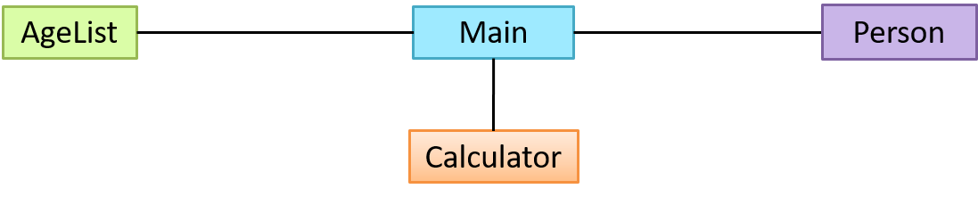
An OO solution is basically a network of objects interacting with each other. Therefore, it is useful to be able to model how the relevant objects are 'networked' together inside a software i.e. how the objects are connected together.
Given below is an illustration of some objects and how they are connected together. Note: the diagram uses an ad-hoc notation.
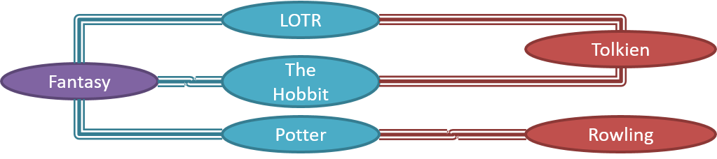
Note that these object structures within the same software can change over time.
Given below is how the object structure in the previous example could have looked like at a different time.
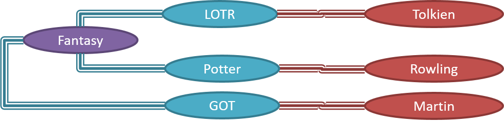
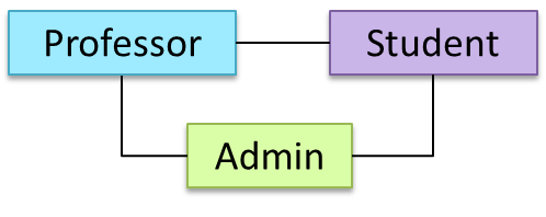
However, object structures do not change at random; they change based on a set of rules, as was decided by the designer of that software. Those rules that object structures need to follow can be illustrated as a class structure i.e. a structure that exists among the relevant classes.
Here is a class structure (drawn using an ad-hoc notation) that matches the object structures given in the previous two examples. For example, note how this class structure does not allow any connection between Genre objects and Author objects, a rule followed by the two object structures above.

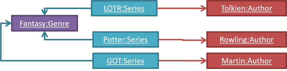
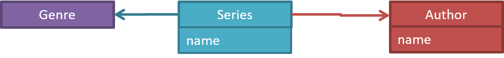
UML Object Diagrams are used to model object structures and UML Class Diagrams are used to model class structures of an OO solution.
Here is an object diagram for the above example:
And here is the class diagram for it:
Design → Modelling → Modelling Structure → Class diagrams - basic
Can use basic-level class diagrams
Contents of the panels given below belong to a different chapter; they have been embedded here for convenience and are collapsed by default to avoid content duplication in the printed version.
UML Class Diagrams → Introduction → What UML/ClassDiagrams
Classes form the basis of class diagrams.
UML Class Diagrams → Classes → What Classes UML Class Diagrams → Class-Level Members → What Class-Level Members
Associations are the main connections among the classes in a class diagram.
OOP Associations → What OOP/Associations UML Class Diagrams → Associations → What UML/Associations
The most basic class diagram is a bunch of classes with some solid lines among them to represent associations, such as this one.
An example class diagram showing associations between classes.
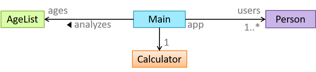
In addition, associations can show additional decorations such as association labels, association roles, multiplicity and navigability to add more information to a class diagram.
UML Class Diagrams → Associations → Labels Labels UML Class Diagrams → Associations → Roles Roles OOP Associations → Multiplicity OOP/Multiplicity UML Class Diagrams → Associations → Multiplicity UML/Multiplicity OOP Associations → Navigability OOP/Navigability UML Class Diagrams → Associations → Navigability UML/Navigability
Here is the same class diagram shown earlier but with some additional information included:
Exercises
Which association notations are shown?
Which association notations are shown in this diagram?
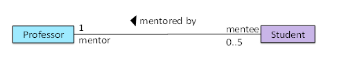
- a. association labels
- b. association roles
- c. association multiplicity
- d. class names
(a) (b) (c) (d)
Explanation: '1’ is a multiplicity, ‘mentored by’ is a label, and ‘mentor’ is a role.
Explain Class Diagram
Explain the associations, navigabilities, and multiplicities in the class diagram below:
Draw Class Diagram for Box etc.
Draw a class diagram for the code below. Show the attributes, methods, associations, navigabilities, and multiplicities.
class Box {
    private Item[] parts = new Item[10];
    private Item spareItem;
    private Lid lid; // lid of this box
    private Box outerBox;

    public void open() {
        // ...
    }
}
class Item {
    public static int totalItems;
}
class Lid {
    Box box; // the box for which this is the lid
}
Design → Modelling → Modelling Structure → Object diagrams
Can use basic object diagrams
UML → Object Diagrams → Introduction Object Diagrams
Object diagrams can be used to complement class diagrams. For example, you can use object diagrams to model different object structures that can result from a design represented by a given class diagram.
UML → Object Diagrams → Objects OD/Objects UML → Object Diagrams → Associations OD/Associations
Exercises
Draw an Object Diagram for Box etc.
This question is based on the following question from another topic:
Draw Class Diagram for Box etc.
Draw a class diagram for the code below. Show the attributes, methods, associations, navigabilities, and multiplicities.
class Box {
    private Item[] parts = new Item[10];
    private Item spareItem;
    private Lid lid; // lid of this box
    private Box outerBox;

    public void open() {
        // ...
    }
}
class Item {
    public static int totalItems;
}
class Lid {
    Box box; // the box for which this is the lid
}
Draw an object diagram to match the code. Include objects of all three classes in your object diagram.
Tools → UML → Object versus class diagrams
Can distinguish between class diagrams and object diagrams
Compared to the notation for class diagrams, object diagrams differ in the following ways:
- Show objects instead of classes:
- Instance name may be shown
- There is a
:before the class name - Instance and class names are underlined
- Methods are omitted
- Multiplicities are omitted
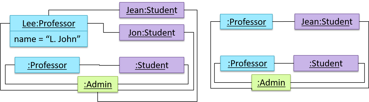
Furthermore, multiple object diagrams can correspond to a single class diagram.
Both object diagrams are derived from the same class diagram shown earlier. In other words, each of these object diagrams shows ‘an instance of’ the same class diagram.
Exercises
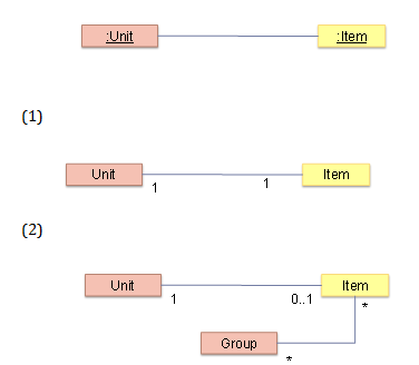
Which class diagrams match the object diagram?
Which of these class diagrams match the given object diagram?
- 1
- 2
(1) (2)
Explanation: Both class diagrams allow one Unit object to be linked to one Item object.
Tools → UML → Notes
Can use UML notes
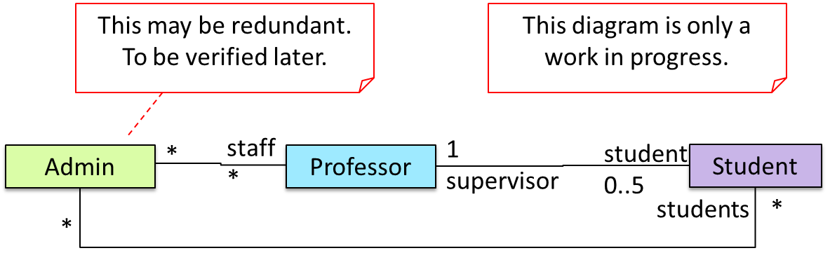
UML notes can augment UML diagrams with additional information. These notes can be shown connected to a particular element in the diagram or can be shown without a connection. The diagram below shows examples of both.
Example:
Tools → UML → Constraints
UML → Notes
Can specify constraints in UML diagrams
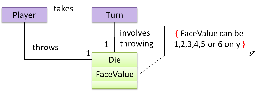
A constraint can be given inside a note, within curly braces. Natural language or a formal notation such as OCL (Object Constraint Language) may be used to specify constraints.
Example:
Tools → UML → Class Diagrams → Associations as attributes
Can show an association as an attribute
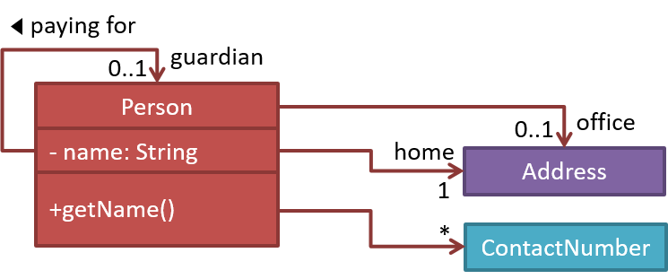
An association can be shown as an attribute instead of a line.
Association multiplicities and the default value can be shown as part of the attribute using the following notation. Both are optional.
name: type [multiplicity] = default value
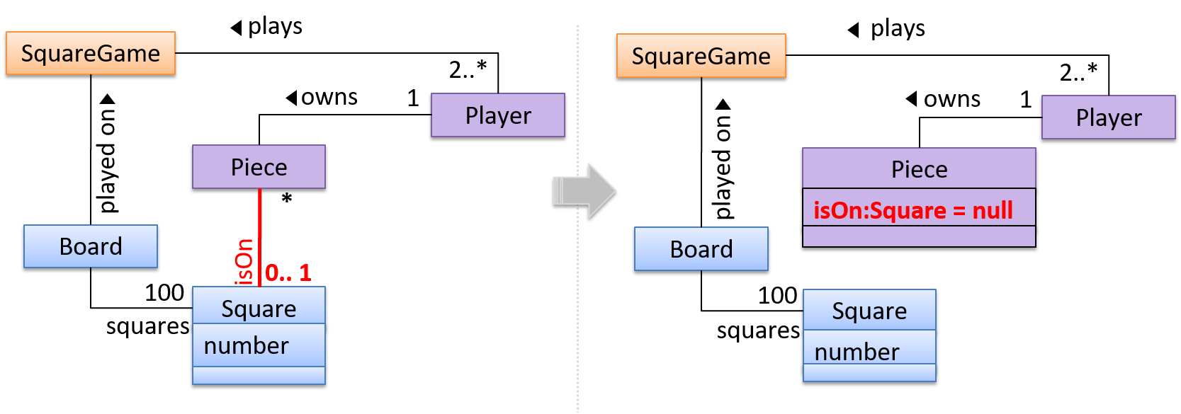
The diagram below depicts a multi-player Square Game being played on a board comprising of 100 squares. Each of the squares may be occupied with any number of pieces, each belonging to a certain player.
A Piece may or may not be on a Square. Note how that association can be replaced by an isOn attribute of the Piece class. The isOn attribute can either be null or hold a reference to a Square object, matching the 0..1 multiplicity of the association it replaces. The default value is null.
The association that a Board has 100 Squares can be shown in either of these two ways:
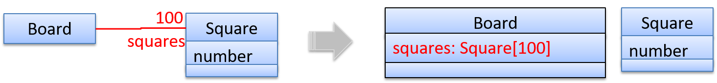
Show each association as either an attribute or a line but not both. A line is preferred as it is easier to spot.
Design → Modelling → Modelling Structure → Class diagrams - intermediate
Design → Modeling → Class Diagrams (Basic)
Can use intermediate-level class diagrams
A class diagram can also show different types of relationships between classes: inheritance, compositions, aggregations, dependencies.
Modeling inheritance
OOP → Inheritance → What OOP/Inheritance UML → Class Diagrams → Inheritance → What UML/Inheritance
Modeling composition
OOP → Associations → Composition OOP/Composition UML → Class Diagrams → Composition → What UML/Composition
Modeling aggregation
OOP → Associations → Aggregation OOP/Aggregation UML → Class Diagrams → Aggregation → What UML/Aggregation
Modeling dependencies
OOP → Associations → Dependencies OOP/Dependencies UML → Class Diagrams → Dependencies → What UML/Dependencies
A class diagram can also show different types of class-like entities:
Modeling enumerations
OOP → Classes → Enumerations OOP/Enumerations UML → Class Diagrams → Enumerations → What UML/Enumerations
Modeling abstract classes
OOP → Inheritance → Abstract Classes OOP/AbstractClasses UML → Class Diagrams → Abstract Classes → What UML/AbstractClasses
Modeling interfaces
OOP → Inheritance → Interfaces OOP/Interfaces UML → Class Diagrams → Interfaces → What UML/Interfaces
Exercises
Statements about class diagram
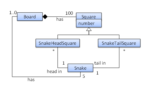
Which of these statements match the class diagram?
- a. A
Snakemust belong to at least oneBoard. - b. A
SnakeHeadSquarecan contain only oneSnakehead. - c. A
Squarecan contain aSnakehead. - d. A
Snakehead can be in more than oneSnakeHeadSquare. - e. The
Boardhas exactly 5Snakes.
(a)(b)(c)(d)(e)
Explanation:
(a) does not match because a Snake may or may not belong to a Board (multiplicity is 0..1)
(b) matches the diagram because the multiplicity given is 1
(c) matches the diagram because SnakeHeadSquare is a Square (due to inheritance)
(d) matches the diagram because the multiplicity given is *
(e) matches the diagram because the multiplicity given is 5
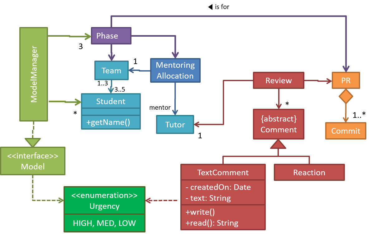
Explain notations in the class diagram
Explain the meaning of various class diagram notations in the following class diagram:
Draw a Class Diagram for the code (StockItem, Inventory, Review, etc.)
Consider the code below:
public interface Billable {
    void bill();
}
public abstract class Item
         implements Billable {
    public abstract void print();
}
public class StockItem extends Item {
    private Review review;
    private String name;

    public StockItem(
        String name, Rating rating) {

        this.name = name;
        this.review = new Review(rating);
    }

    @Override
    public void print() {
        //...
    }

    @Override
    public void bill() {
        //...
    }
}
public enum Rating {
    GOOD, OK, POOR
}
public class Review {
    private final Rating rating;

    public Review(Rating rating) {
        this.rating = rating;
    }
}
import java.util.List;

public class Inventory {
    private List<Item> items;

    public int getItemCount() {
        return items.size();
    }

    public void generateBill(Billable b) {
        // ...
    }

    public void add(Item s) {
        items.add(s);
    }
}
(a) Draw a class diagram to represent the code. Show all attributes, methods, associations, navigabilities, visibilities, known multiplicities, and association roles. Show associations as lines.
(b) Draw an object diagram to represent the situation where the inventory has one item named spanner and a review of POOR rating
i.e., new Inventory().add(new StockItem("spanner", new Review(Rating.POOR))).
Paradigms → OOP → Associations → Association classes
Can explain the meaning of association classes
An association class represents additional information about an association. It is a normal class but plays a special role from a design point of view.
A Man class and a Woman class are linked with a ‘married to’ association and there is a need to store the date of marriage. However, that data is related to the association rather than specifically owned by either the Man object or the Woman object. In such situations, an additional association class can be introduced, e.g. a Marriage class, to store such information.
UML Class Diagrams → Association Classes → What UML/AssociationClasses
Implementing association classes
There is no special way to implement an association class. It can be implemented as a normal class that has variables to represent the endpoint of the association it represents.
In the code below, the Transaction class is an association class that represents a transaction between a Person who is the seller and another Person who is the buyer.
class Transaction {

    //all fields are compulsory
    Person seller;
    Person buyer;
    Date date;
    String receiptNumber;

    Transaction(Person seller, Person buyer, Date date, String receiptNumber) {
        //set fields
    }
}
Exercises
Which are suitable as an Association Class?
Which of these are suitable as an Association Class?
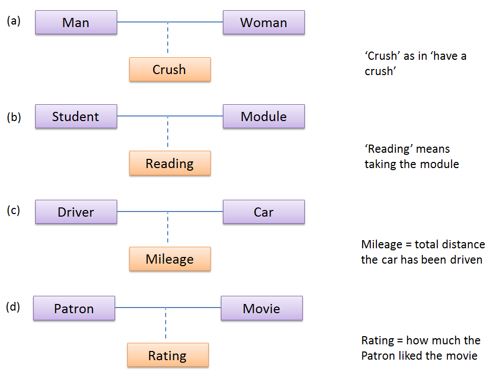
- a
- b
- c
- d
(a)(b)(c)(d)
Explanation: Mileage is a property of the car, and not specifically about the association between the Driver and the Car. If Mileage was defined as the total number of miles that car was driven by that driver, then it would be suitable as an association class.
Design → Modelling → Modelling Structure → Object oriented domain models
Can explain object oriented domain models
The analysis process for identifying objects and object classes is recognized as one of the most difficult areas of object-oriented development. --Ian Sommerville, in the book Software Engineering
Class diagrams can also be used to model objects in the the relevant information that needs to be examined to understand a problemproblem domain (i.e. to model how objects actually interact in the real world, before emulating them in the solution). Class diagrams that are used to model the problem domain are called conceptual class diagrams or OO domain models (OODMs).
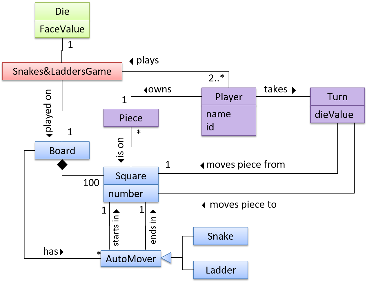
The OO domain model of a snakes and ladders game is given below.
Description: The snakes and ladders game is played by two or more players using a board and a die. The board has 100 squares marked 1 to 100. Each player owns one piece. Players take turns to throw the die and advance their piece by the number of squares they earned from the die throw. The board has a number of snakes. If a player’s piece lands on a square with a snake head, the piece is automatically moved to the square containing the snake’s tail. Similarly, a piece can automatically move from a ladder foot to the ladder top. The player whose piece is the first to reach the 100th square wins.
OODMs do not contain solution-specific classes (i.e. classes that are used in the solution domain but do not exist in the problem domain). For example, a class called DatabaseConnection could appear in a class diagram but not usually in an OO domain model because DatabaseConnection is something related to a software solution but not an entity in the problem domain.
OODMs represents the class structure of the problem domain and not their behavior, just like class diagrams. To show behavior, use other diagrams such as sequence diagrams.
OODM notation is similar to class diagram notation but omit methods and navigability.
Exercises
This diagram is,...
This diagram is,
- a. A class diagram.
- b. An object diagram.
- c. An OO domain model, also known as a conceptual class diagram.
- d. Can be either a class diagram or an OO domain model.
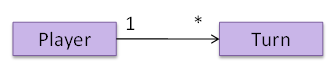
(a)
Explanation: The diagram shows navigability which is not shown in an OO domain model. Hence, it has to be a class diagram.
Difference between a class diagram and an OO domain model?
What is the main difference between a class diagram and an OO domain model?
(a)
Explanation: Both are UML diagrams, and use the class diagram notation. While it is true that often a class diagram may have more classes and more details, the main difference is that the OO domain model describes the problem domain while the class diagram describes the solution.
Design → Modelling → Modelling Behaviors Sequence diagrams - basic
Can draw basic sequence diagrams
UML Sequence Diagrams → Introduction UML/SequenceDiagrams
UML Sequence Diagrams → Basic Notation UML/SD/Basic
UML Sequence Diagrams → Loops UML/SD/Loops UML Sequence Diagrams → Object Creation UML/SD/Creation
UML Sequence Diagrams → Minimal Notation UML/SD/Minimal
Exercises
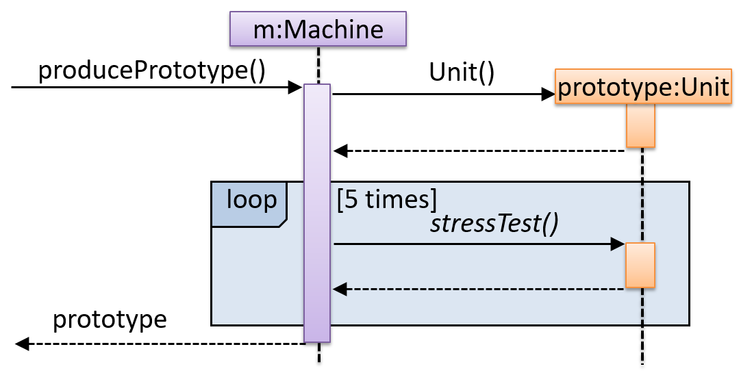
Explain Sequence Diagram about Machine
Explain in your own words the interactions illustrated by this Sequence Diagram:
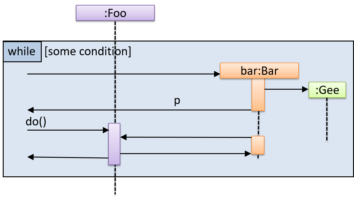
Draw a Sequence Diagram for the code (PersonList, Person, Tag)
Consider the code below:
class Person {
    Tag tag;
    String name;

    Person(String personName, String tagName) {
        name = personName;
        tag = new Tag(tagName);
    }
}
class Tag {
    Tag(String value) {
        // ...
    }
}

class PersonList {
    void addPerson(Person p) {
        // ...
    }
}
Draw a sequence diagram to illustrate the object interactions that happen in the code snippet below:
PersonList personList = new PersonList();
while (hasRoom) {
    Person p = new Person("Adam", "friend");
    personList.addPerson(p);
}
Find notation errors in Sequence Diagram
Find notation mistakes in the sequence diagram below:
Design → Modelling → Modelling Behaviors Sequence diagrams - intermediate
Can draw intermediate-level sequence diagrams
UML Sequence Diagrams → Object Deletion UML/SD/Deletion UML Sequence Diagrams → Self-Invocation UML/SD/Self-Invocation UML Sequence Diagrams → Alternative Paths UML/SD/Alternative UML Sequence Diagrams → Optional Paths UML/SD/Optional
UML Sequence Diagrams → Calls to Static Methods
UML/SD/StaticMethods
Method calls to static (i.e., class-level) methods are received by the class itself, not an instance of that class. You can use <<class>> to show that a participant is the class itself.
In this example, m calls the static method Person.getMaxAge() and also the setAge() method of a Person object p.
Here is the Person class, for reference:
Exercises
What’s going on here?
What’s going on here?
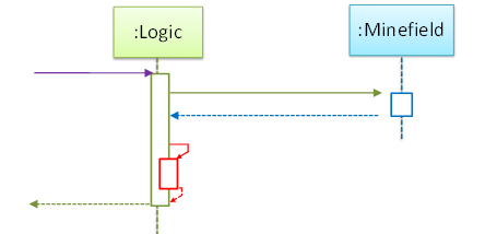
- a.
Logicobject is executing a parallel thread. - b.
Logicobject is executing a loop. - c.
Logicobject is creating anotherLogicinstance. - d. One of
Logicobject’s methods is calling another of its methods. - e.
Minefieldobject is calling a method ofLogic.
(d)
Explain Sequence Diagram (ParserFactory)
Explain the interactions depicted in this sequence diagram.
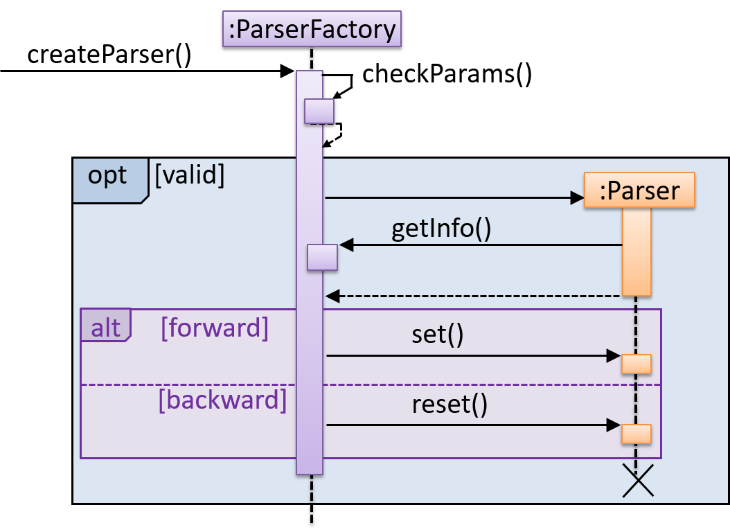
First, the createParser() method of an existing ParserFactory object is called. Then, ...
Draw Sequence Diagram for printing a quote
Draw a sequence diagram to represent this code snippet.
if (isFirstPage) {
    new Quote().print();
}
The Quote class:
class Quote {

    String q;

    Quote() {
        q = generate();
    }

    String generate() {
        // ...
    }

    void print() {
        System.out.println(q);
    }

}
- Show
new Quote().print();as two method calls. - As the created Quote object is not assigned to a variable, it can be considered as 'deleted' soon after its
print()method is called.
Tools → UML → Sequence Diagrams → Reference frames
Can interpret sequence diagrams with reference frames
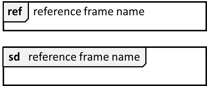
UML uses ref frame to allow a segment of the interaction to be omitted and shown as a separate sequence diagram. Reference frames help you to break complicated sequence diagrams into multiple parts or simply to omit details you are not interested in showing.
Notation:
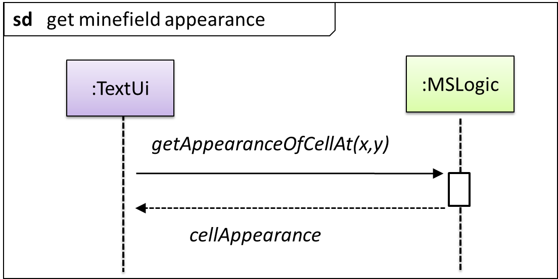
The details of the get minefield appearance interactions have been omitted from the diagram.
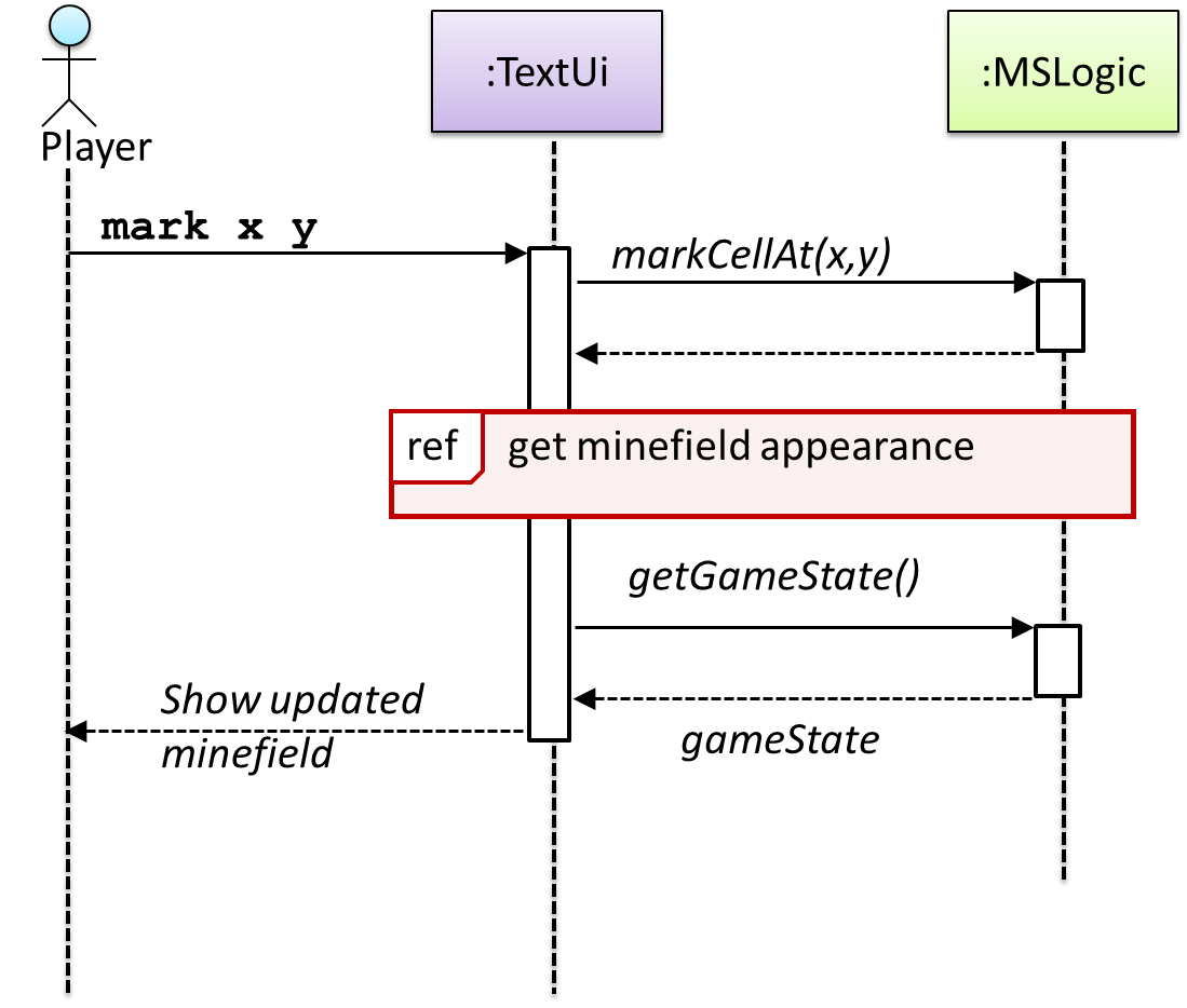
Those details are shown in a separate sequence diagram given below.
Tools → UML → Sequence Diagrams → Parallel paths
Can interpret sequence diagrams with parallel paths
UML uses par frames to indicate parallel paths.
Notation:
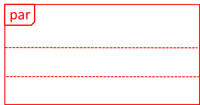
Logic is calling methods CloudServer#poll() and LocalServer#poll() in parallel.
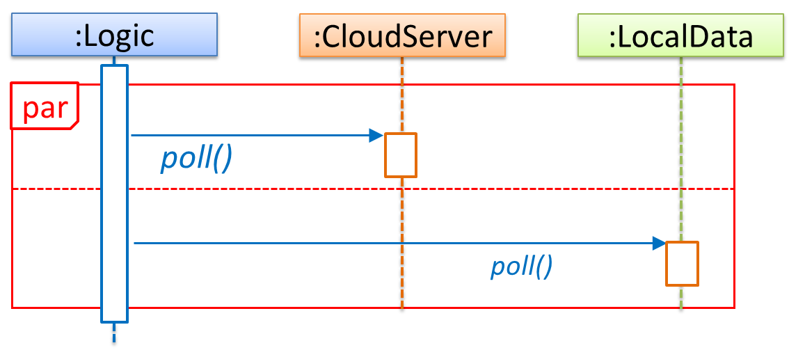
If you show parallel paths in a sequence diagram, the corresponding Java implementation is likely to be multi-threaded because a normal Java program cannot do multiple things at the same time.
Design → Modelling → Modelling Behaviors Activity diagrams - basic
Can use basic-level activity diagrams
Software projects often involve workflows. Workflows define the a connected sequence of stepsflow in which a process or a set of tasks is executed. Understanding such workflows is important for the success of the software project.
Some examples in which a certain workflow is relevant to software project:
A software that automates the work of an insurance company needs to take into account the workflow of processing an insurance claim.
The algorithm of a piece of code represents the workflow (i.e. the execution flow) of the code.
UML Activity Diagrams → Introduction → What UML/AD/Intro
UML Activity Diagrams → Basic Notation → Linear Paths UML/AD/LinearPaths
UML Activity Diagrams → Basic Notation → Alternate Paths UML/AD/AlternatePaths
UML Activity Diagrams → Basic Notation → Parallel Paths UML/AD/ParallelPaths
Exercises
Which sequences are not allowed?
Which of these sequences of actions is not allowed by the given activity diagram?
- i. start a b c d end
- ii. start a b c d e f g c d end
- iii. start a b c d e g f c d end
- iv. start a b c d g c d end
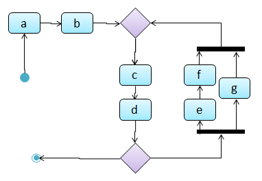
(iv)
Explanation: -e-f- and -g- are parallel paths. Both paths should complete before the execution reaches c again.
Model the algorithms of calculating grades
(a) Draw an activity diagram to represent the following algorithm used for calculating the grade of a student.
- Read project score from keyboard
- Read exam score from keyboard
- Calculate the total
- Calculate the grade
- Print total and grade
(b) Update the activity diagram you drew above to also include the following logic that is used when calculating the grade.
A: at least 25 marks for each component and at least 60 in total (for brevity, you can call thiscondition-A-- i.e., ifcondition-Ais met, give gradeA)B: at least one component has 25 or more marks and at least 50 in total (i.e.,condition-B)C: otherwise
(c) Update the diagram you drew above to incorporate the following information.
- At the very beginning, ask the user how many grades need to be calculated.
- Repeat the whole grade calculation process for the number of times specified by the user.
Example Activity Diagram

Model workflow of a Burger shop
Draw an activity diagram to represent the following workflow a burger shop uses when processing an order by a customer.
- First, a cashier takes the order.
- Then, three workers start preparing the order at the same time; one prepares the drinks, one prepares the burgers, and one prepares the desserts.
- In the meantime, the customer pays for the order. If the customer has a voucher, she pays using the voucher; otherwise she pays using cash.
- After paying, the customer collects the food after all three parts of the order are ready.
Example Activity Diagram
Design → Modelling → Modelling Behaviors Activity diagrams - intermediate
Can use intermediate-level activity diagrams
UML Activity Diagrams → Intermediate Notation → Rakes UML/AD/Rakes
UML Activity Diagrams → Intermediate Notation → Swim Lanes UML/AD/SwimLanes